

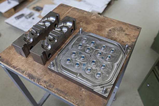
Precision plastic component buyers, medical device engineers, and high-volume electronics procurement officers constantly demand absolute consistency across mass-production runs. Because scaling up production requires maximizing efficiency, deploying a high-quality multi-cavity injection mold is the industry standard for reducing piece part costs. However, technical manufacturing teams frequently encounter frustrating weight and size deviations during early test shots, raising a critical quality-control question: “We are running a four-cavity mold, but the molded parts from each cavity exhibit different weights and dimensions. What is causing this imbalance, and how can we guarantee that every single cavity produces identical parts?”
Sourcing a poorly balanced mold leads to high scrap rates, inconsistent assembly fitment, and constant press-side troubleshooting. Understanding the fluid dynamics and thermal properties of multi-cavity tooling allows your engineering team to secure highly reliable production. This technical guide analyzes the root causes of cavity imbalance, outlines precise runner balancing techniques, and provides strategic checkpoints to de-risk your custom tooling purchases.
1. The Physics of Imbalance: Why Multi-Cavity Parts Differ in Weight and Size
To solve weight and dimension variations, your technical team must first analyze the behavior of molten polymer as it travels through the mold. In a perfect manufacturing setup, the plastic melt front must reach the gates of every single cavity at the same microsecond, under identical pressure and temperature. When this fails to occur, the mold experiences filling imbalance, which directly causes part-to-part weight fluctuations.
Three primary engineering variables typically trigger this filling imbalance:
-
Variations in Flow Path Lengths: If the molten plastic travels different distances to reach different cavities, the cavities closer to the sprue will pack first, becoming heavier and denser than the outer cavities.
-
Microscopic Machining Tolerances: Even tiny, micron-level differences in runner diameters or gate sizes can cause significant flow imbalances. This occurs because fluid flow resistance is highly sensitive to channel thickness.
-
Uneven Cooling Rates: If one side of the mold core runs slightly hotter than the other, the plastic in the hotter cavities will shrink more during cooling, altering the final part dimensions.
2. Engineering Balanced Runners: Designing for Identical Cavity Pressure
Eliminating cavity-to-cavity variations requires mold designers to focus heavily on the configuration of the runner system.
Naturally Balanced Runner Layouts
The most effective way to guarantee balanced filling is to utilize a naturally balanced (or geometrically symmetrical) runner layout. This design ensures that the flow path from the main sprue to every single cavity is physically identical in length, diameter, and number of turns. Because the melt encounters the same flow resistance along every branch, the cavities fill simultaneously, minimizing weight and size variations.
The Limits of Artificial Balancing
When space constraints force engineers to use an asymmetrical (or artificially balanced) runner layout, they must adjust the runner and gate sizes of each branch to make up for the differing path lengths. While mold flow software can calculate these diameter adjustments, this method remains highly sensitive to small changes in material viscosity and melt temperature. If the press operator adjusts the barrel heat or injection speed slightly, the artificial balance can quickly fall apart, leading to renewed part weight variations.
3. Strategic Sourcing Guidelines for Tooling Buyers
Corporate procurement managers can protect their manufacturing quality and secure stable production runs by incorporating three strict validation steps into their tooling contracts:
-
Demand a Comprehensive Mold Flow Analysis Report: Do not authorize mold steel cutting without reviewing a detailed mold flow simulation. Ensure the report confirms that the filling time deviation between the fastest and slowest cavities is less than or equal to 5% under standard operating parameters.
-
Specify Independent Temperature Control for High-Precision Parts: For ultra-critical parts like medical connectors, avoid cold runners. Invest in a hot runner system featuring independent temperature controllers for each drop to guarantee precise thermal uniformity.
-
Incorporate Short-Shot Testing into Mold Trials: During the mold trial phase (T1), require the factory to perform a short-shot analysis by gradually reducing the injection volume. Weighing these partially filled parts provides clear, physical proof of how evenly the melt fills each cavity.
Conclusion: Secure Flawless Multi-Cavity Tooling Performance
In conclusion, maintaining strict dimensional uniformity across all parts requires a highly balanced mold design that combines symmetrical runners, precise gate sizing, and uniform cooling lines.
Stop wasting your manufacturing budget, production time, and material on poorly balanced multi-cavity tools that produce inconsistent parts and drive up scrap rates. Upgrading your tooling program to our high-performance multi-cavity injection mold systems guarantees absolute cavity balance, uniform part weights, and highly repeatable dimensions across every cycle. We optimize every runner path and verify every mold design using advanced mold flow analysis to ensure your production lines run flawlessly. Contact our custom tooling engineering division today to submit your part 3D files and receive a detailed, comprehensive manufacturing proposal.






Add comment