

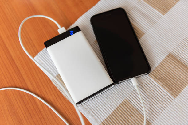
An injection molded power bank housing does more than protect a portable charging device. Its structure affects assembly efficiency, PCB positioning, USB-C port alignment, surface appearance, durability, and manufacturing cost.
For OEM buyers, selecting a custom plastic housing manufacturer requires more than reviewing exterior styling or comparing tooling quotations. The enclosure must accommodate the battery pack, circuit board, connectors, switches, and internal supports while remaining suitable for injection molding and repeatable mass production.
A well-planned power bank enclosure design addresses parting lines, snap fits, screw bosses, wall thickness, assembly clearances, and dimensional tolerances before mold fabrication begins. Early design-for-manufacturing (DFM) review helps identify potential problems while changes are still easier to implement.
This guide explains the key structural decisions OEM buyers should review before approving a custom power bank housing for tooling.
1. Define the Internal Layout Before Designing the Exterior
A power bank enclosure must accommodate several components within a limited space. The exterior shape should therefore follow the internal packaging requirements rather than being designed independently.
Identify the Critical Components
Before finalizing the enclosure, establish the dimensions and locations of the main internal components:
- Battery cells or battery pack.
- Printed circuit board (PCB).
- USB-C input and output connectors.
- Additional output ports, switches, and indicator lights.
- Display windows or light pipes, where required.
- Insulation, protective barriers, and internal supports.
- Fasteners and assembly features.
The exact component arrangement depends on the electrical architecture and product specification. Battery dimensions, connector locations, and PCB mounting holes should be confirmed before the enclosure geometry is finalized.
Create a Reliable Component Reference Model
OEM buyers should provide a 3D assembly model or accurate component drawings whenever possible. The housing designer can then evaluate clearances, interference risks, assembly access, and the available space for structural features.
A useful design review checks whether:
- The PCB can be positioned without interfering with the housing.
- The connectors align with their external openings.
- The battery pack fits within the approved internal envelope.
- Wires and connectors have sufficient routing space.
- Fasteners and assembly tools can reach their intended locations.
- Internal features avoid unwanted pressure on sensitive components.
For battery-powered products, the enclosure design must also accommodate the specified battery protection and thermal requirements. Structural supports should not crush, puncture, or apply unintended loads to the battery pack.
OEM takeaway: Confirm the internal layout before approving the external housing. Changing a connector or PCB position after tooling begins may affect several related features at once.
2. Design the Upper and Lower Housing for Reliable Assembly
Many power bank enclosures use two main plastic parts: an upper shell and a lower shell. Their interface must support accurate alignment, secure fastening, acceptable seam appearance, and efficient assembly.
Choose the Right Parting Line
The parting line is where the mold separates to release the molded component. Its position affects the enclosure’s appearance, mold complexity, and the visibility of any mismatch between the two halves.
When reviewing the parting line, consider:
- Whether it crosses a prominent exterior surface.
- Whether it interferes with decorative details or printed graphics.
- Whether the upper and lower shells align consistently.
- Whether the geometry can be molded and released without unnecessary tooling complexity.
- Whether the seam can accommodate the required assembly method.
A well-positioned parting line can help keep visible seams away from prominent surfaces. However, the optimal location depends on the enclosure geometry and mold design.
Define the Shell Alignment Features
Alignment features help position the two housing halves during assembly. Depending on the design, these may include locating pins, recesses, stepped interfaces, or other interlocking geometry.
The design should account for the dimensional variation of both molded parts. If alignment features are too tight, assembly may become difficult. If they are too loose, the housing may show uneven seams or movement.
The appropriate geometry depends on the material, part dimensions, molding process, and required fit. It should be evaluated through DFM review and sample testing rather than selected from a universal clearance value.
Consider the Assembly Sequence
A housing that looks straightforward in a 3D model may be difficult to assemble if the PCB, battery pack, and connectors must be installed in an impractical order.
Before finalizing the shell interface, confirm:
- Which components enter the lower shell first.
- How the PCB is secured and connected.
- How the battery pack is positioned.
- Whether the upper shell can close without pinching wires.
- How the two halves are fastened.
- Whether inspection and repair remain practical.
Assembly sequence should be part of the enclosure design review, not an afterthought during mass production.
3. Snap Fits vs. Screw Bosses: Select the Right Fastening Structure
Snap fits and screw bosses are common features in custom injection molded plastic enclosures. Each offers different advantages, and some products use both.
Snap-Fit Design for Faster Assembly
A snap fit uses elastic deformation and an interlocking feature to hold components together. It can reduce the need for separate fasteners and support efficient assembly.
However, snap-fit performance depends on the material, beam geometry, deflection, root radius, molding direction, and assembly conditions.
During design review, assess:
- Whether the snap arm can deflect without exceeding the material’s allowable strain.
- Whether the hook geometry provides sufficient engagement.
- Whether the root area creates a stress concentration.
- Whether the feature can be molded and released correctly.
- Whether the snap fit will withstand the expected assembly and service conditions.
Not every plastic grade is equally suitable for repeated snap-fit deflection. Material selection and geometry must be considered together.
For housings that may need servicing, determine whether the snaps should be reusable or whether the enclosure is intended for one-time assembly.
Screw Bosses for Mechanical Retention
Screw bosses provide mounting points for screws that join housing parts or secure internal components. They can be useful where a more defined fastening method is required.
Key design considerations include:
- Boss diameter and height.
- Screw type and engagement requirements.
- Boss wall thickness relative to surrounding walls.
- Distance from adjacent walls and ribs.
- Support against installation torque.
- Clearance for the screw head and assembly tool.
A boss that is too weak may crack during fastening. An oversized or poorly connected boss may create sink marks on the exterior surface or increase local cooling differences.
The design should also distinguish between screws that form threads directly in plastic and screws used with inserts or other fastening systems. Each approach has different structural and assembly requirements.
Can Snap Fits and Screws Be Combined?
Yes. A snap fit can help align the housing halves while screws provide final retention. This arrangement may suit products requiring controlled assembly or additional mechanical security.
However, the combination increases the number of features that must be designed and inspected. Buyers should assess whether the additional fastening method is necessary for the product’s expected use and service requirements.
| Design Factor | Snap Fit | Screw Boss |
|---|---|---|
| Assembly | Can support fast assembly | Requires screw installation |
| Additional hardware | May not require separate fasteners | Usually requires screws or related hardware |
| Design sensitivity | Sensitive to material and deflection | Sensitive to boss geometry and fastening loads |
| Serviceability | Depends on whether the snap can be released repeatedly | Can support disassembly if designed appropriately |
| Common risks | Broken hooks, excessive strain, loose engagement | Cracked bosses, stripped threads, sink marks |
The final choice should follow the required assembly method, product life, maintenance needs, material selection, and cost target.
4. Position PCB Mounting Bosses Without Creating Molding Defects
PCB mounting bosses help locate and secure the circuit board inside the power bank housing. Their position directly affects connector alignment, assembly access, and the space available for other components.
Match the Bosses to the PCB Drawing
Use the PCB’s actual mounting-hole locations rather than estimating them from a visual reference.
The design review should confirm:
- Mounting-hole coordinates and diameters.
- Screw or insert specifications.
- Clearance around electronic components.
- Space for connectors and cable routing.
- PCB alignment with the housing openings.
- Access for fastening and inspection.
If the PCB is positioned by multiple bosses, the tolerance stack-up should be checked to avoid forcing the board into place.
Control Boss Geometry and Local Wall Thickness
A thick boss connected directly to a thin exterior wall can cool differently from the surrounding plastic. This may create visible sink marks or contribute to local deformation.
To reduce the risk, designers may use supporting ribs, appropriate boss proportions, and controlled transitions between thick and thin sections.
The correct geometry depends on the selected resin, part dimensions, gate location, and molding conditions. There is no single boss-to-wall ratio that guarantees a defect-free result for every housing.
Avoid Unintended Stress on the PCB
The mounting system should hold the board securely without bending it or applying unnecessary force to solder joints and connectors.
Where the design uses multiple mounting points, review the tolerance relationship between the PCB, bosses, and connector openings. A small positional mismatch can become significant when several components must align simultaneously.
For OEM projects, PCB and housing design teams should review the same assembly model before tooling approval.
5. Design Accurate USB-C Openings and Connector Clearances
USB-C openings are critical interface features in a power bank enclosure. If the opening is too small, the connector may be difficult to insert. If it is too large or poorly positioned, the product may look unfinished or expose unnecessary internal space.
Use the Actual Connector and PCB Position
The external opening should be based on the connector’s dimensional drawing and its final position in the assembled product.
Important checks include:
- Opening width, height, and corner geometry.
- Connector center position relative to the housing.
- Plug insertion and removal clearance.
- PCB mounting tolerances.
- Housing wall thickness around the opening.
- Space for adjacent ports, buttons, and indicator lights.
If the connector is mounted on the PCB, the opening must account for both PCB placement and connector manufacturing tolerances.
A port opening should not be dimensioned solely from a generic USB-C reference image. Confirm the selected connector’s actual mechanical envelope.
Allow for Assembly and Manufacturing Tolerances
The final connector position depends on the combined tolerances of the PCB, connector, housing, and assembly features.
A practical tolerance review considers the complete stack rather than assigning clearance to the opening in isolation.
For example, a connector may sit slightly off-center because of PCB positioning variation. The opening must still provide acceptable plug access across the permitted tolerance range.
Designers should also check whether the housing edge interferes with the connector shell or the plug body during insertion.
Consider Reinforcement Around the Port
Repeated plugging and unplugging can place mechanical loads near the connector opening. If the surrounding housing wall is too weak, the area may deform or crack under certain conditions.
Depending on the design, local ribs or other support features may help distribute loads. These features must not interfere with connector access or create excessive local thickness.
The required strength depends on the product’s intended use and validation criteria. Prototype testing should confirm that the port area performs as expected.
6. Maintain Suitable Wall Thickness to Reduce Sink Marks and Warpage
Wall thickness is one of the most important considerations in injection molded power bank housing design. Uneven or unnecessarily thick sections can increase cooling differences, prolong cycle time, and contribute to visible defects.
Why Uniform Wall Thickness Matters
Plastic generally shrinks as it cools. If different sections of a part cool at different rates, the resulting shrinkage may be uneven.
Potential consequences include:
- Sink marks above thick internal features.
- Warpage or dimensional distortion.
- Uneven seam alignment.
- Changes in connector or PCB positioning.
- Longer cooling times and reduced production efficiency.
A consistent wall structure helps make cooling and shrinkage more predictable, although it does not eliminate every molding defect.
Avoid Unnecessary Thick Sections
Designers should avoid adding material simply to make a housing feel stronger. Local thickness increases may create more molding challenges than a carefully designed rib or support structure.
Where additional stiffness is required, consider whether ribs, corner reinforcement, or revised geometry can provide the needed performance without creating large solid sections.
Ribs also require appropriate draft, spacing, and thickness to support mold filling and release. Their dimensions should be evaluated against the chosen material and the part’s geometry.
Manage Sink Marks Around Bosses and Ribs
Bosses and ribs are often necessary, but their connections to the main wall need careful design.
Potential improvements include:
- Reducing excessive local thickness.
- Using appropriately proportioned ribs.
- Avoiding large solid intersections.
- Reviewing gate position and expected flow.
- Checking the appearance of the opposite exterior surface.
Sink marks may still depend on material shrinkage, packing conditions, cooling, and tooling. DFM review helps identify risk areas, but trial molding and process optimization are needed to verify the final result.
Understand Warpage Risk
Warpage can result from uneven shrinkage, differences in cooling, material orientation, geometry, and residual stress.
For a two-piece power bank enclosure, warpage may affect more than appearance. It can also change seam gaps, connector alignment, and the fit of the PCB or battery pack.
The DFM review should therefore examine dimensional stability at critical interfaces, not just whether the exterior surface appears flat.
7. Check Draft Angles, Ribs, and Mold Release
A housing may have a sound assembly design but still be difficult to manufacture if the geometry does not support mold release.
Add Draft Where the Geometry Requires It
Draft angles help molded parts release from the mold. The required amount depends on material behavior, surface texture, wall depth, and tooling conditions.
Textured surfaces often require more draft than smooth surfaces. Deep vertical walls and certain internal features may also need special consideration.
Before tooling, identify surfaces that could cause sticking, scuffing, or difficult ejection. Confirm the draft requirements with the mold designer rather than applying one angle to every surface.
Use Ribs to Support Large Panels
Large flat surfaces may require ribs or other structural features to improve stiffness. However, rib placement and thickness can affect surface appearance, cooling, and mold filling.
A useful design review checks:
- Whether the panel needs additional support.
- Whether ribs create thick intersections.
- Whether ribs interfere with internal components.
- Whether sufficient draft is provided.
- Whether the exterior surface could show sink marks.
The goal is to meet structural requirements while maintaining a moldable and visually acceptable part.
Review Undercuts and Tooling Complexity
Some features may prevent a part from releasing directly from a simple mold. Undercuts can require slides, lifters, or other tooling mechanisms.
These mechanisms may increase mold complexity, cost, maintenance needs, and production cycle time.
If a side opening, clip, or recessed feature creates an undercut, ask whether the design can be adjusted without compromising function. A small geometry change may simplify tooling, but the decision should account for appearance and assembly requirements.
8. Conduct a DFM Review Before Mold Fabrication
Design for manufacturability (DFM) is a structured review of whether a part can be produced consistently using the intended manufacturing process.
For OEM buyers, DFM should happen before the mold design is finalized. Changes made after steel cutting may require additional machining, mold modification, or new validation samples.
What Should a Power Bank Housing DFM Review Cover?
| DFM Review Item | Key Questions |
|---|---|
| Parting line | Is the location suitable for appearance and mold release? |
| Draft angles | Can the part release without unacceptable damage or sticking? |
| Wall thickness | Are there unnecessary thick sections or abrupt transitions? |
| Snap fits | Are material strain and engagement requirements suitable? |
| Screw bosses | Can the bosses withstand assembly loads without excessive sink risk? |
| PCB mounting | Do the mounting points match the approved PCB drawing? |
| USB-C opening | Is connector alignment maintained across the tolerance stack? |
| Shrinkage and warpage | Which features are most sensitive to dimensional variation? |
| Gate and runner design | Can the planned filling approach support acceptable part quality? |
| Mold complexity | Are slides, lifters, or other mechanisms necessary? |
| Material selection | Does the resin meet the required strength, appearance, and operating conditions? |
| Quality inspection | Which dimensions and visual features require defined acceptance criteria? |
Approve the 3D Model and Critical Dimensions
Before mold fabrication, buyers should confirm the latest approved 3D model, 2D drawings, material specification, and assembly requirements.
Identify critical dimensions separately from noncritical cosmetic features. Typical critical interfaces may include PCB mounting points, connector openings, fastening features, and the seam between housing halves.
The design should also define acceptable cosmetic defects and the intended surface finish. Terms such as “smooth,” “tight fit,” or “no visible sink marks” may need clearer acceptance criteria to avoid disputes.
Use Prototype and Trial-Molding Feedback
A DFM review reduces foreseeable risks, but it cannot replace physical validation.
Depending on project requirements, prototype parts or initial molded samples can be used to evaluate fit, assembly sequence, connector access, appearance, and dimensional accuracy.
After trial molding, review actual measurements and observed defects before authorizing mass production. Any design changes should be reflected in the controlled drawing and approved model.
9. Frequently Asked Questions
What is the most important design consideration for an injection molded power bank housing?
The most important consideration is the relationship between the internal component layout, enclosure geometry, and manufacturing process. PCB mounting, connector alignment, wall thickness, fastening features, and mold release all need to work together.
How thick should a power bank plastic housing be?
There is no universal wall thickness for every power bank housing. The appropriate value depends on the resin, part dimensions, structural requirements, surface appearance, and molding process. A DFM review should evaluate wall uniformity and local thick sections before tooling.
Are snap fits better than screws for power bank enclosures?
Neither method is always better. Snap fits can support faster assembly, while screws can provide defined mechanical retention and may support servicing. The choice depends on material properties, product life, assembly needs, and structural requirements.
How can designers reduce sink marks and warpage in injection molded housings?
Start by reviewing wall thickness, thick intersections, boss and rib geometry, gate location, and expected cooling behavior. Validate the design through mold trials and dimensional inspection because final results also depend on material and process conditions.
Why should OEM buyers complete DFM before opening the mold?
DFM can identify potential problems with mold release, wall thickness, fastening features, connector openings, and dimensional tolerances before tooling is finalized. Addressing these issues early can reduce avoidable mold changes and improve the path to stable production.
What files should buyers provide to a custom plastic housing manufacturer?
Provide a 3D model, 2D drawings, internal component specifications, PCB dimensions, connector locations, material preferences, surface finish requirements, target volume, and quality criteria. More complete information allows the supplier to assess the design and quote the project more accurately.
Conclusion: Good Enclosure Design Starts Before Tooling
A reliable injection molded power bank housing depends on more than its exterior shape. Upper and lower shell alignment, snap fits, screw bosses, PCB mounting points, USB-C access, wall thickness, draft angles, and mold release all influence assembly and production quality.
For OEM buyers, the most effective approach is to coordinate mechanical design, component placement, material selection, and molding requirements before approving tooling. A structured DFM review helps identify risks early, while prototype assembly and trial molding provide the evidence needed to validate the design.
When evaluating a custom plastic housing manufacturer, look for a clear engineering review process, documented design changes, and a practical plan for validating critical dimensions. WIN WIN supports custom injection molded component projects based on buyer drawings and specifications, with final design, tooling, and production details confirmed during technical review and quotation.




Add comment