

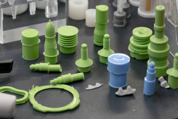
During plastic injection molding production, surface defects, dimensional changes, and structural issues are common concerns for manufacturers. Many customers ask: “Are defects such as sink marks, flow marks, and weld lines caused by material problems or product design issues?”
The answer is usually related to multiple factors, including:
- Part design
- Mold structure
- Material characteristics
- Injection parameters
- Cooling conditions
Understanding common injection molding defects helps manufacturers identify root causes and improve product quality before mass production.
A professional custom injection molding service should analyze defects from the entire molding process rather than adjusting only machine settings.
What Causes Sink Marks in Injection Molded Parts?
How Can Sink Mark Prevention Improve Surface Quality?
A sink mark is a surface depression that occurs when thicker areas of a plastic part shrink during cooling.
During injection molding:
- The outer surface cools and solidifies first.
- The inner thick section continues shrinking.
- Internal material contraction pulls the surface inward.
- A visible depression appears.
Common causes include:
- Uneven wall thickness
- Excessive rib thickness
- Insufficient holding pressure
- Inadequate cooling time
How to Prevent Sink Marks?
Effective sink mark prevention methods include:
Maintain Uniform Wall Thickness
Consistent wall thickness allows more balanced cooling and reduces uneven shrinkage.
Optimize Rib Design
For reinforcing ribs:
- Rib thickness should generally remain below approximately 60% of the main wall thickness
- Avoid excessive material accumulation
Adjust Injection Parameters
Manufacturers can improve results by optimizing:
- Holding pressure
- Holding time
- Cooling time
Proper parameter adjustment reduces internal shrinkage and improves surface appearance.
Why Does Warpage Occur in Plastic Parts?
What Causes Injection Molding Warpage?
Warpage occurs when different areas of a molded part shrink at different rates.
The resulting internal stress releases after ejection, causing:
- Bending
- Twisting
- Dimensional distortion
Common causes include:
- Uneven wall thickness
- Uneven cooling
- Incorrect mold temperature distribution
- Improper gate location
What Is an Effective Warpage Solution for Plastic Parts?
A reliable warpage solution for plastic parts requires controlling both design and manufacturing factors.
Optimize Product Design
Important improvements include:
- Maintaining consistent wall thickness
- Reducing unnecessary material concentration
- Improving structural symmetry
Use Simulation Analysis
Before production, manufacturers can use:
- Mold flow analysis
- Finite element analysis (FEA)
- Cooling simulation
These tools help predict deformation trends and optimize mold design.
Improve Cooling System Design
Adjusting cooling channel layout can create more uniform heat removal and reduce thermal stress.
How Do Weld Lines Affect Injection Molded Products?
Why Do Weld Lines Appear?
Weld lines form when two separate melt flows meet inside the mold cavity.
They usually appear around:
- Holes
- Inserts
- Multiple gate locations
- Complex geometry areas
At the meeting point, polymer chains may not fully bond, causing:
- Reduced mechanical strength
- Visible surface marks
- Lower appearance quality
How Can Weld Line Quality Be Improved?
Manufacturers can improve weld lines through:
Adjusting Gate Location
Changing gate positions can control where melt fronts meet.
A weld line located in a non-critical area can reduce product performance risks.
Increasing Mold Temperature
Higher mold temperatures help maintain melt flow ability and improve polymer bonding.
Increasing Injection Speed
Faster filling can improve melt fusion before cooling begins.
What Causes Ejector Marks on Plastic Parts?
How Do Top White Marks and Scratches Form?
Ejector marks, also called ejector whitening or drag marks, occur during part removal from the mold.
Common causes include:
- Insufficient draft angle
- Excessive ejection force
- Poor ejector pin positioning
- Improper ejection timing
These defects often appear as:
- White stress marks
- Surface scratches
- Local deformation
How Can Ejector Marks Be Reduced?
Solutions include:
Increase Draft Angle
A suitable draft angle helps the part release smoothly.
Optimize Ejector Pin Design
Improvements include:
- Increasing ejector contact area
- Adjusting ejector pin positions
- Balancing ejection force
Improve Ejection Sequence
Optimizing timing prevents excessive stress during demolding.
Why Do Flash Defects Appear in Injection Molding?
What Causes Injection Molding Flash?
Flash occurs when molten plastic escapes from the mold parting line.
Common causes include:
- Insufficient clamping force
- Mold wear
- Excessive injection pressure
- Damaged parting surfaces
The result is unwanted thin plastic edges around the product.
How Can Injection Molding Flash Be Prevented?
Manufacturers can reduce flash by:
- Selecting sufficient clamping force
- Maintaining mold surfaces
- Checking mold alignment
- Optimizing injection pressure
Regular mold inspection is especially important for high-volume production.
What Causes Air Traps and Burn Marks?
How Does Trapped Air Create Burn Marks?
Air traps occur when air inside the cavity cannot escape during filling.
As molten plastic compresses trapped air:
- Temperature rises rapidly
- Polymer material may degrade
- Dark burn marks appear
Common locations include:
- End of filling areas
- Deep cavities
- Closed structural sections
How Can Air Traps Be Eliminated?
Effective solutions include:
Improve Venting Design
Adding or optimizing exhaust grooves allows trapped air to escape.
Adjust Gate Position
Better gate placement can improve melt flow direction.
Optimize Filling Parameters
Adjusting injection speed and pressure helps achieve smoother filling.
Common Injection Molding Defects and Solutions
Quick Reference Guide for Manufacturers
| Defect | Main Cause | Prevention Method |
|---|---|---|
| Sink Marks | Uneven cooling shrinkage | Uniform wall thickness, optimized ribs |
| Warpage | Uneven shrinkage and internal stress | Mold flow analysis, improved cooling |
| Weld Lines | Melt flow joining points | Adjust gates, increase mold temperature |
| Ejector Marks | Excessive ejection stress | Improve draft angle and ejector design |
| Flash | Insufficient clamping or mold wear | Increase clamping control, maintain molds |
| Burn Marks | Trapped air compression | Improve venting and gate design |
How Should Manufacturers Prevent Injection Molding Defects?
A Quality Control Approach From Design to Production
Preventing defects requires cooperation between:
Product Design
Focus on:
- Wall thickness
- Rib structure
- Draft angles
- Material selection
Mold Design
Consider:
- Gate location
- Cooling channels
- Venting system
- Ejection structure
Process Optimization
Control:
- Injection pressure
- Temperature settings
- Cooling time
- Holding pressure
Early analysis reduces modification costs and improves production consistency.
Understanding Root Causes Improves Injection Molding Quality
Common injection molding defects are rarely caused by a single factor. Sink marks, warpage, weld lines, flash, and air traps usually result from the interaction between part design, mold structure, material behavior, and process conditions.
Effective defect prevention starts before production through optimized design, simulation analysis, and controlled molding parameters.
For manufacturers requiring stable quality and repeatable production, selecting an experienced custom injection molding service with strong engineering capabilities is essential for reducing defects and improving overall manufacturing efficiency.
WIN WIN provides customized injection molding solutions, supporting product development, mold optimization, and production quality control for different plastic component applications.


Add comment