

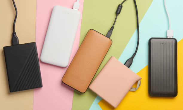
Reliable power bank plastic injection molding requires more than producing a housing with the correct shape. The enclosure must meet dimensional, cosmetic, mechanical, and assembly requirements. Even small molding defects can affect product appearance, button alignment, charging port positioning, and final assembly.
For power bank brands, electronics manufacturers, and OEM buyers, common concerns include sink marks, weld lines, flash, warpage, flow marks, and visible ejector-pin marks. These defects often result from interactions between material selection, mold design, processing parameters, and product geometry.
A structured quality control system helps identify problems before mass production. This guide explains the injection molding workflow, common enclosure defects, precision mold design considerations, and practical QC inspection standards for custom power bank housings.
1. The Injection Molding Workflow for Electronics Enclosures
Power bank housings often require thin walls, compact structures, precise openings, and attractive surface finishes. These requirements make process control important throughout production.
A typical plastic injection molding workflow includes material preparation, mold setup, injection, packing, cooling, ejection, trimming, and inspection.
1.1 Raw Material Selection and Drying
Material selection should match the product’s mechanical, thermal, cosmetic, and regulatory requirements.
Common plastics for electronic enclosures include:
| Material | General characteristics | Potential application |
|---|---|---|
| ABS | Good processability, impact resistance, and surface finishing options | General power bank housings |
| PC | High impact resistance and heat resistance, depending on grade | More demanding electronic enclosures |
| ABS+PC | Combines selected properties of both materials | Enclosures requiring a balance of toughness and processability |
| PP | Lightweight and chemically resistant | Selected structural components |
| PA | Good mechanical properties, with moisture sensitivity depending on grade | Selected internal or structural parts |
The final choice should consider wall thickness, drop requirements, operating environment, surface finish, and compatibility with secondary processes.
Material drying is another important step. Some resins absorb moisture and require controlled drying before molding.
For example, PC and PA grades commonly require moisture control. Improper drying can cause splay marks, bubbles, or other surface and processing problems.
Buyers should request the material grade, supplier data sheet, and recommended processing conditions. Drying temperature and time should follow the resin manufacturer’s instructions.
1.2 Mold Setup and Injection Parameter Adjustment
After material preparation, operators install the mold and configure the injection molding machine.
Key parameters include:
- Barrel temperature.
- Mold temperature.
- Injection speed.
- Injection pressure.
- Holding pressure.
- Holding time.
- Screw speed.
- Back pressure.
- Cooling time.
These parameters interact with each other. A change in one setting can affect filling, shrinkage, surface appearance, and cycle time.
For example, insufficient holding pressure may contribute to sink marks. Excessive injection pressure may increase flash risk when the mold has insufficient clamping force or poor sealing.
The correct process window depends on material grade, part geometry, mold design, and machine capability.
1.3 Injection, Packing, and Cooling
The injection molding cycle generally includes several stages.
Stage 1: Filling
Molten plastic enters the mold cavity through the runner and gate system. Injection speed and pressure influence how the material fills the cavity.
Stage 2: Packing and holding
After the cavity fills, additional pressure compensates for material shrinkage as the plastic begins to cool.
The gate eventually freezes, limiting further material flow into the cavity. Holding pressure and time must therefore be matched to the part and gate design.
Stage 3: Cooling
The plastic solidifies inside the mold. Cooling channels remove heat and help the part maintain its shape.
Uneven cooling can contribute to residual stress, dimensional variation, and warpage.
Stage 4: Ejection
The mold opens, and the ejection system releases the molded part. Ejector locations and force distribution influence the risk of visible marks or deformation.
1.4 Why Process Stability Matters for Mass Production
A successful first sample does not guarantee consistent mass production.
Changes in resin batches, machine conditions, mold temperatures, and production environments can affect the final result.
A stable manufacturing process should include:
- Approved material specifications.
- Documented machine settings.
- Controlled mold temperature.
- Consistent cooling conditions.
- Defined first-piece inspection.
- Regular in-process quality checks.
- Recorded process changes.
For OEM power bank projects, buyers should approve a reference sample and confirm the production process before releasing large orders.
2. Common Injection Defects in Power Bank Cases and Solutions
Injection molding defects can affect both the appearance and functionality of electronic enclosures.
The most effective corrective action depends on identifying the underlying cause. Simply changing machine settings may not solve a problem caused by poor wall thickness design or an unsuitable gate location.
2.1 Sink Marks
Common causes include:
- Excessive wall thickness variation.
- Insufficient packing pressure.
- Short holding time.
- Poor gate location or early gate freezing.
- Inadequate cooling.
Possible corrective actions:
- Keep wall thickness as uniform as practical.
- Reduce excessive material around ribs and bosses.
- Optimize gate size and position.
- Adjust holding pressure and time.
- Review cooling channel design.
For power bank housings, sink marks are particularly noticeable on broad, smooth exterior surfaces. Designers should review ribs and mounting bosses before finalizing the mold.
2.2 Weld Lines
Weld lines form when two or more melt fronts meet but do not bond sufficiently.
They may appear around openings, holes, inserts, and other features that divide the material flow.
Potential causes include:
- Low melt or mold temperature.
- Insufficient injection speed.
- Poor gate location.
- Inadequate venting.
- Complex flow paths.
- Material degradation.
Possible solutions include:
- Adjusting gate location.
- Improving venting near the weld-line region.
- Optimizing melt and mold temperatures.
- Reviewing injection speed and pressure.
- Simplifying the flow path where possible.
Not every weld line can be eliminated. Its appearance and mechanical significance should be evaluated against the product’s acceptance criteria.
For cosmetic power bank cases, weld lines should receive special attention on visible surfaces.
2.3 Flash
Flash is excess plastic that escapes from the mold cavity and forms a thin edge or film along the parting line or other mold interfaces.
Common causes include:
- Insufficient clamping force.
- Excessive injection pressure.
- Damaged or worn mold surfaces.
- Incorrect mold alignment.
- Contamination on the parting surface.
- Excessive mold separation under pressure.
Corrective actions include checking clamping force, reducing excessive injection pressure, cleaning mold surfaces, and repairing worn parting areas.
Flash around charging ports, button openings, and assembly edges can interfere with fitment. These areas should have clear dimensional and visual acceptance requirements.
2.4 Warpage
Warpage occurs when a molded part bends, twists, or changes shape after cooling.
Typical causes include:
- Uneven cooling.
- Non-uniform wall thickness.
- Different shrinkage rates across the part.
- Residual molding stress.
- Poor gate positioning.
- Inappropriate ejection conditions.
Possible solutions include:
- Improve wall thickness consistency.
- Optimize cooling channel layout.
- Review gate location and material flow.
- Adjust packing and cooling parameters.
- Improve mold temperature balance.
- Review ejection positions and forces.
Warpage is especially important for power bank housings because the upper and lower shells must fit together.
Even small dimensional changes may create uneven gaps, loose joints, or interference during assembly.
2.5 Splay Marks, Flow Marks, and Color Differences
Other cosmetic defects may affect the finished enclosure.
| Defect | Typical appearance | Possible cause | Control approach |
|---|---|---|---|
| Splay marks | Silvery streaks or surface lines | Moisture, volatile gases, or material contamination | Control drying and material handling |
| Flow marks | Visible flow patterns | Uneven filling, temperature variation, or flow behavior | Optimize filling and mold temperature |
| Color variation | Differences between parts or batches | Material variation, pigment dispersion, or processing changes | Control resin and color masterbatch |
| Burn marks | Darkened areas near the end of flow | Trapped gas or excessive local heating | Improve venting and review injection conditions |
| Ejector marks | Visible circles or raised/recessed areas | Ejection pressure or unsuitable pin placement | Optimize ejector design and ejection conditions |
Color matching should be based on an approved reference sample or defined color measurement method.
For customized power bank housings, buyers should confirm whether the required finish is molded-in color, painting, coating, or another surface treatment.
2.6 How to Prevent Defects Before Mass Production
Defect prevention should begin during design and mold development.
A practical prevention process includes:
- Reviewing part geometry and wall thickness.
- Conducting mold flow analysis when appropriate.
- Checking gate and runner design.
- Reviewing cooling channel layout.
- Confirming resin drying requirements.
- Establishing a stable process window.
- Inspecting the first molded samples.
- Validating complete housing assembly.
This approach reduces the risk of discovering structural or cosmetic problems after the mold enters mass production.
3. Precision Mold Design for Seamless Enclosure Assembly
Mold design directly affects dimensional accuracy, surface quality, production stability, and assembly performance.
Power bank housings commonly include upper and lower shells, charging ports, button openings, LED indicator windows, screw bosses, and internal locating features.
These details require careful mold engineering.
3.1 Parting Line Selection
The parting line is the boundary where the two mold halves meet.
Its position influences:
- Visible surface appearance.
- Flash risk.
- Mold complexity.
- Part removal.
- Dimensional accuracy.
- Secondary finishing requirements.
For consumer electronics enclosures, the parting line should be positioned to minimize visible defects and simplify assembly.
Buyers should review the proposed parting line in the mold design before tooling begins.
3.2 Gate Position and Material Flow
The gate is the opening through which molten plastic enters the mold cavity.
Its location affects filling balance, pressure distribution, weld-line formation, shrinkage, and surface appearance.
Common gate types include:
| Gate type | General characteristics | Typical consideration |
|---|---|---|
| Edge gate | Simple design and relatively easy processing | May leave a visible gate mark |
| Pin-point gate | Small gate mark and suitable for selected multi-cavity molds | Requires appropriate mold structure |
| Submarine gate | Can support automatic gate separation | Requires careful design and material consideration |
| Fan gate | Spreads material flow across a wider entrance | Useful for selected wide or flat parts |
The appropriate gate depends on part geometry, resin properties, cosmetic requirements, and mold structure.
For power bank cases, gate marks should not interfere with visible surfaces, assembly edges, or functional openings.
3.3 Ejection System Design
After cooling, the molded part must be released from the mold without excessive deformation or surface damage.
Common ejection components include:
- Ejector pins.
- Ejector sleeves.
- Stripper plates.
- Lifter mechanisms.
- Other customized release structures.
Ejector locations should distribute the release force appropriately.
Poorly positioned ejector pins may create visible marks or local deformation. Thin walls and deep ribs can also make ejection more difficult.
During mold review, buyers should confirm:
- Ejector locations.
- Ejector mark visibility.
- Release direction.
- Draft angles.
- Risk of part deformation.
- Compatibility with the enclosure’s cosmetic requirements.
3.4 Dimensional Tolerance and Assembly Fit
A power bank housing may look correct individually but still fail during assembly.
For example, small dimensional deviations can affect:
- USB-A or USB-C port alignment.
- Button movement.
- LED indicator positioning.
- PCB mounting.
- Battery compartment clearance.
- Upper and lower shell fit.
- Screw boss alignment.
Buyers should identify critical-to-quality dimensions before tooling.
A useful dimensional drawing should specify:
- Overall length, width, and height.
- Wall thickness.
- Hole and opening dimensions.
- Mounting positions.
- Flatness requirements.
- Assembly clearances.
- Critical tolerances.
Tolerance values should be based on part geometry, material shrinkage, mold capability, and assembly requirements. Avoid applying unnecessarily tight tolerances to every dimension.
3.5 Mold Flow Analysis and Design Validation
For complex or thin-wall enclosures, mold flow analysis can help predict filling behavior and identify potential design issues.
Depending on the project, analysis may evaluate:
- Melt filling patterns.
- Weld-line locations.
- Air traps.
- Pressure distribution.
- Cooling behavior.
- Predicted shrinkage and warpage.
Simulation results are not a substitute for physical sampling. Actual molding conditions and material behavior must still be validated.
For demanding projects, design review, simulation, trial molding, and assembly testing should form one continuous validation process.
4. Quality Control Standards for Mass-Produced Housings
A clear QC inspection standard helps buyers and manufacturers evaluate power bank plastic cases consistently.
The inspection plan should define sampling methods, test conditions, measurement tools, acceptance criteria, and defect classifications.
4.1 Define A-Surface and B-Surface Inspection Requirements
A common approach is to classify enclosure surfaces according to their visibility and functional importance.
| Surface category | Typical area | Inspection focus |
|---|---|---|
| A-surface | Main visible exterior surfaces | Scratches, dents, sink marks, color differences, flow marks |
| B-surface | Less visible exterior or side surfaces | Flash, ejector marks, assembly edges, minor cosmetic defects |
| C-surface | Internal or hidden surfaces | Structural integrity, cracks, burrs, mounting features, functional dimensions |
The exact surface classification should be confirmed in the product drawing.
For example, a charging port edge may be less visible but highly important for assembly and user experience. It may therefore require stricter dimensional criteria than its surface category suggests.
4.2 Visual Inspection and Defect Classification
Visual inspection should use consistent conditions.
The inspection specification should define:
- Lighting conditions.
- Viewing distance.
- Viewing angle.
- Inspection duration.
- Reference samples.
- Acceptable defect size and quantity.
- Surface-specific acceptance limits.
A defect classification system may include:
Critical defects: Conditions that create safety risks, prevent essential functions, or violate mandatory requirements.
Major defects: Problems that affect assembly, product function, or clearly visible appearance.
Minor defects: Small cosmetic variations that do not affect functionality and remain within approved limits.
Buyers should define these categories with the manufacturer rather than relying on vague descriptions such as good appearance or no obvious defects.
4.3 Dimensional Inspection and Tolerance Control
Dimensional inspection confirms that the molded housing matches the approved drawing.
Common inspection tools include:
- Digital calipers.
- Micrometers.
- Height gauges.
- Coordinate measuring machines (CMM).
- Go/no-go gauges.
- Custom assembly fixtures.
Important inspection points may include:
| Inspection item | Purpose |
|---|---|
| Overall dimensions | Confirm housing size |
| Wall thickness | Check structural consistency |
| Port openings | Verify connector alignment |
| Screw boss positions | Confirm PCB and shell assembly |
| Mounting features | Check component positioning |
| Flatness | Reduce gaps and assembly interference |
| Shell fit | Verify upper and lower housing compatibility |
The inspection report should record measured values, drawing tolerances, and pass/fail results.
For dimensions with strict requirements, buyers may request a first article inspection report before mass production.
4.4 Cross-Cut Adhesion Test for Painted Housings
Some power bank housings use spray painting, UV coating, or other surface treatments.
A cross-cut adhesion test can help evaluate coating adhesion to the substrate.
The test generally involves:
- Preparing the coated surface.
- Making a specified grid of cuts through the coating.
- Applying the specified test tape.
- Removing the tape under controlled conditions.
- Evaluating coating removal according to the selected test method.
Relevant standards include ISO 2409 and ASTM D3359. They use different procedures and rating systems, so their results should not be treated as directly interchangeable.
The applicable method, coating system, substrate, test conditions, and acceptance rating should be agreed before production.
Cross-cut testing is not normally a meaningful acceptance test for an uncoated, molded-in-color plastic surface.
4.5 Functional Assembly Inspection
Appearance and dimensional measurements alone cannot confirm that the complete enclosure works correctly.
For power bank cases, assembly inspection should cover:
- PCB installation.
- Battery compartment clearance.
- Charging port alignment.
- Button travel and operation.
- LED indicator visibility.
- Screw fastening.
- Shell joining and gap consistency.
- Internal component interference.
Where the housing uses snap-fit structures, buyers should also evaluate engagement, retention, and repeated assembly performance.
The inspection plan should reflect the actual product assembly process.
4.6 Establishing a Practical QC Inspection Plan
A complete inspection plan can divide quality checks into three stages.
| Inspection stage | Main checks | Purpose |
|---|---|---|
| Incoming material inspection | Resin grade, color, material condition, documentation | Prevent unsuitable materials from entering production |
| In-process inspection | Molding appearance, critical dimensions, process stability | Identify production variation early |
| Final inspection | Appearance, dimensions, assembly, packaging, and agreed tests | Verify shipment conformity |
For sampling, buyers may use an agreed AQL-based plan where appropriate. However, AQL is a sampling acceptance method, not a guarantee that every shipped part is defect-free.
Critical safety or functional characteristics may require additional controls or 100% inspection, depending on the risk assessment.
5. What Buyers Should Confirm Before Ordering Custom Power Bank Housings
Before mass production, buyers should provide a complete technical package.
A practical procurement checklist includes:
5.1 Product and Material Information
- Product dimensions and 3D drawings.
- Selected resin and material grade.
- Required color and surface finish.
- Wall thickness and structural requirements.
- Intended operating environment.
- Mechanical and drop-test requirements, if applicable.
5.2 Mold and Manufacturing Requirements
- Mold structure and parting line.
- Gate location and gate type.
- Ejector system.
- Required production quantity.
- Expected tooling and maintenance arrangements.
- Approved sample and revision control.
5.3 Quality and Acceptance Requirements
- A/B/C surface definitions.
- Visual inspection conditions.
- Critical dimensions and tolerances.
- Color reference and allowable variation.
- Assembly requirements.
- Coating adhesion test method, if applicable.
- Sampling plan and defect classification.
- Packaging and shipment inspection requirements.
A complete specification reduces ambiguity between product designers, procurement teams, and injection molding manufacturers.
6. Frequently Asked Questions
Q1: What plastic materials are commonly used for power bank injection molding?
ABS, PC, and ABS+PC are common options for electronic housings. The appropriate material depends on impact resistance, heat resistance, appearance, processing behavior, and cost. Buyers should confirm the exact resin grade before tooling.
Q2: Why do sink marks appear on injection molded power bank cases?
Sink marks often result from uneven wall thickness, insufficient packing, early gate freezing, or inadequate cooling. Improving rib design, gate configuration, holding conditions, and cooling balance can help reduce them.
Q3: How can manufacturers reduce weld lines in plastic enclosures?
Manufacturers can review gate positions, improve mold venting, and optimize injection and mold temperatures. Part geometry also influences melt flow. Some weld lines may remain, so their appearance and strength should be evaluated against project requirements.
Q4: What causes warpage in injection molded electronic housings?
Warpage can result from uneven cooling, non-uniform shrinkage, residual stress, and unsuitable ejection conditions. Mold design and processing parameters should be reviewed together to improve dimensional stability.
Q5: What is the difference between AQL and 100% inspection?
AQL-based inspection uses a defined sampling plan to make lot acceptance decisions. 100% inspection checks every unit for specified characteristics. Neither approach replaces good process control, and critical product requirements may need additional verification.
Q6: Is a cross-cut adhesion test necessary for every power bank housing?
No. Cross-cut adhesion testing applies to suitable coated surfaces, such as painted or coated housings. It is generally not relevant to uncoated molded-in-color plastic parts. The test method and acceptance criteria should match the coating system.
Q7: What should buyers inspect before approving mass production?
Buyers should inspect the approved sample’s appearance, critical dimensions, material, color, assembly fit, and relevant functional requirements. For painted housings, coating adhesion may also require testing. The approved sample and inspection specification should become the production reference.
Conclusion: Connect Mold Design, Process Control, and QC
Reliable power bank plastic injection molding depends on controlling the complete manufacturing process.
Material selection and drying establish the foundation. Injection, packing, and cooling parameters influence the final part quality. Precision mold design helps manage material flow, ejection, and dimensional accuracy. A structured QC inspection plan verifies appearance, dimensions, coating performance, and assembly fit.
For OEM buyers, the most effective approach is to define technical requirements before tooling, validate samples under realistic conditions, and establish measurable acceptance criteria before mass production.
Win-Win provides custom plastic injection molding services for customized components and electronic product housings. Share your drawings, material requirements, and inspection expectations with our team to discuss your project.




Add comment