

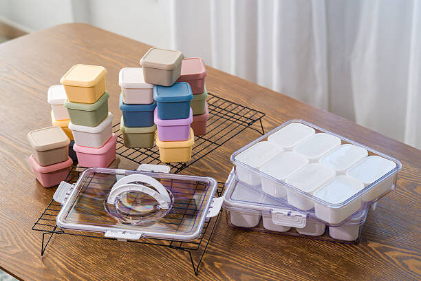
In the competitive food packaging and housewares industries, high-volume thin-wall injection molding represents the pinnacle of manufacturing efficiency. Producing lightweight, durable, and stackable lunch boxes requires wall thicknesses often dropping below 0.6mm. Because these parts must fill in milliseconds under immense injection pressures, standard mold construction methodologies will inevitably fail.
When configuring a thin-wall mold design, minor oversights in gate geometry or thermal management will lead to catastrophic defects like part deformation, short shots, burning, or prolonged cycle times that drain your profit margins. This engineering guide breaks down the four critical architectural details—Gating, Cooling, Venting, and Ejection—required to ensure high-speed, zero-defect production.
1. Gating System Design: Achieving Uniform, High-Velocity Filling
Thin-wall structures offer high resistance to molten plastic flow. To prevent the melt from freezing before completing the fill, the gating array must be highly optimized.
   [Hot Runner Drop] ──> [Balanced Needle Valve Gate] ──> [Symmetrical Multi-Point Fill]
                                                                  │
                                                        (Uniform Fluid Wall Advance)
-
Hot Runner Configurations: Traditional cold runners are completely impractical for thin-wall operations due to pressure drops and material waste. Utilizing a premium hot runner for thin-wall setups—specifically a balanced valve-gate system—is non-negotiable.
-
Gate Position & Quantity: For rectangular or multi-compartment lunch boxes, multi-point direct gating or optimized fan gates are positioned to ensure the flow front advances symmetrically. Symmetrical filling guarantees that the fluid front reaches the perimeter extremities simultaneously, preventing core shift or flashing on one side of the mold.
-
Minimizing Flow Length-to-Thickness Ratio ($L/T$): The number of hot runner drops must be engineered to keep the $L/T$ ratio within the processing limits of the polyolefin material (typically Polypropylene for food containers, requiring an $L/T$ ratio under 250:1).
2. Thermal Management: Injection Mold Cooling Optimization
Because cooling accounts for up to 70% to 80% of the total injection cycle time, reducing the part’s thermal energy quickly is the most direct path to increasing output. The relationship between part thickness and cooling time is dictated by Fourier’s law of heat conduction:
As the wall thickness shrinks, the target cooling speed must accelerate exponentially to prevent the thin container from warping upon ejection.
Advanced Conformal Cooling Channels
Standard straight-drilled water lines cannot follow the complex, deep-draw geometric profiles of a lunch box core and cavity. Premium lunch box mold engineering solves this by utilizing 3D-printed conformal cooling mold inserts. These custom fluid pathways trace the exact profile of the container wall at a constant distance, eliminating thermal hotspots and ensuring uniform volumetric shrinkage.
Strategic Beryllium Copper Integration
In areas where 3D-printed channels are mechanically constrained—such as long, narrow core towers or deep ribs—beryllium copper inserts are deployed. Featuring a thermal conductivity rating up to 4 to 5 times higher than standard tool steel, beryllium copper acts as a thermal highway, pulling heat away from the plastic skin instantly to rapidly freeze the part structure.
3. Precision Venting: Eliminating Dieseling and Air Traps
Thin-wall molding forces massive volumes of air out of the cavity in fractions of a second. If this trapped gas cannot escape, the extreme compression drives up localized temperatures, causing part burns (dieseling) or incomplete filling.
-
Sizing the Vent Grooves: To prevent flash while allowing gases to escape freely, vent depths must be machined with extreme accuracy. For standard Polypropylene lunch boxes, primary vents are held strictly between 0.02mm and 0.03mm deep.
-
Perimeter and Ejector Venting: Relying on parting-line vents alone is insufficient. Molds must incorporate venting slots around the full perimeter of the container lip, supplemented by micro-flatted ejector pins that vent the bottom face of the core.
-
CAE Moldflow Analysis: Before cutting tool steel, engineers utilize advanced Moldflow simulations to map the final convergence zones of the melt front, pinpointing potential gas traps so that active venting inserts can be integrated directly into those specific coordinate zones.
4. Ejection and Steel Selection: Demanding Mechanical Reliability
Thin-wall parts lack structural rigidity when hot, making them highly susceptible to puncturing or stress-whitening during the ejection sequence.
[High-Speed Core Retraction] ──> [Stripper Plate + Air Assist Activation] ──> [Deflection-Free Release]
-
Stripper Plate + Air Assist Integration: Relying solely on small mechanical ejector pins can cause the thin bottom of the container to puncture or deform. Instead, thin-wall lunch box molds utilize a continuous stripper plate acting on the perimeter ring, paired with a high-pressure pneumatic air-blast valve popping through the core center to break the internal vacuum during release.
-
Draft Angles: To ease release and minimize cycle friction, polished cosmetic vertical faces require a minimum draft angle of ≥ 0.5°. If the container features a textured or textured-grip exterior pattern, the draft requirement scales up to ≥ 1.5° to prevent drag marks.
-
Tool Steel Selection Matrix: Thin-wall molding pressures regularly exceed 1,500 bar, demanding robust steel selections to prevent deflection.
| Mold Component | Material Selected | Hardness / Performance Benefit |
| Cavity Plate Base | P20 / 718H Steel | High structural rigidity, excellent support backing |
| Core & Cavity Inserts | H13 / S136 ESR | HRC 48-52, mirror-polishable, corrosion-resistant |
| Hotspot Core Tips | Beryllium Copper Array | Ultra-high thermal dissipation, fast cooling cycle |
| Stripper Plate Guide | High-Tensile Tool Steel | Hardened wear plates to withstand multi-million cycles |





Add comment